Woodworking Talk banner

Delta Unisaw Power Switch Wiring

1 reading
15K views 94 replies 8 participants last post by  Steve Neul  
#1 ·
I'll preface this with saying that I am an amateur when it comes to electronics, but I'm confident that this is a doable DIY with some guidance. I was just gifted a Delta Unisaw model 34-802 from 1999. It is 230v, single phase, 3HP motor (12.7 amps). The original power switch is broken and I need to replace it, but I'm struggling with the wiring.

There are 4 wires coming into the junction box at the original switch, Black, White, Red, and Green. The green is grounded to the junction box. Black and Red are connected to normally closed poles. White is connected to a normally open pole, and the red and white wires are bridged by a metal bar. I have no idea if this is correct, but this is how the saw came to me.
Image


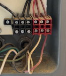
My understanding is that this is a low-voltage switch and the main power is in this larger box at the back of the saw:
Image


I've got a paddle switch just like this one lying around but I'm not totally clear on how to wire it up, or if it would even work given that the original switch has 3 wires going into it and all of the diagrams I've seen for these paddle switches have 4. Can someone help me understand what is going on here and how to approach the next steps? Will this switch work or do I need to look for something else? https://www.grizzly.com/products/woodstock-paddle-switch-120-230v/d4151

Image


I should add that I found this post with what appears to be the same electronics as my saw, but their switch is wired differently: https://www.woodworkingtalk.com/threads/delta-unisaw-electrical-problem.225844/post-2180881
Image


Any help would be much appreciated!
 
#3 · (Edited)
The first picture in my post is my switch without the faceplate installed. The two "pins" that the buttons of the face plate would press are missing. The fourth picture in my post is someone else's switch, also with faceplate removed, showing the red and green "pins" that are absent on my switch.

Images below are the faceplate that came with my saw:
Image
Image


Yes, the diagram in the third picture is from my saw.

The more I look at the control box of my saw the more I think that a previous owner messed around with the wiring. For example, those two yellow wirecaps... haven't seen anything like that in the images of other control boxes that I've been looking at. Looks as though the electromagnet mechanism and switch contacts are being bypassed..?
 
#4 ·
the circuit is a traditional stop start. I believe the control voltage is stepped down by the transformer probably 24 volts. Pressing the start button picks up the motor contactor which seals in. Pressing the stop button breaks the circuit and the motor relay drops out. On the Delta drawing the start/stop station is shown as terminals 1,2,3.
 
#5 ·
Do you have a volt meter? There should be one closed contact and one open contact on the push buttons ( with power off of course ). Do that with the new switch Take the wires off the old switch and check for open/closed as well. Then it’s a matter of matching the wires.

Also check the voltage of the control circuit. It should be OK to apply power. Hopefully no one has really messed around with the wiring.

if all goes well with power on you might try pushing the buttons with an insulated screw driver where the missing pins are.

I will have another look at your pictures. The small red box in the lower right are the control wires to the stop/start station
 
#8 ·
Guessing here but this why the red wire has been moved.

Essentially the start button is bypassed. As soon as power is applied the machine runs. Pressing the stop button would temporarily stop the machine but would immediately restart when released. So to control they must have added another power switch. The paddle switch you linked would be a good choice.
 
#9 ·
I was looking at this more last night and I came to the same conclusion, I think the saw would power up as soon as it is plugged in and only stop when the plug is removed. I haven’t tested this yet but if you think it’s safe to do so I can give it a quick try just to confirm the theory. Is it ok to be bypassing most of the components like this?
 
#10 ·
Those two “wire caps” mar connectors. Do they go into that what looks like a cable at the bottom? Where does that cable go? To a switch perhaps? Another guess here if I’m right that could tie into the control circuit and is how they override the normal start/stop function which is bypassed with the red wire in wrong place at the push buttons. If there is such a switch then when it’s open position the machine will not run.

Horses ass of setup just to avoid replacing a broken push button switch. LOL
 
#11 ·
Right now the wires from the plug go strait to the motor bypassing the switch circuit entirely. For better or worse, the previous owner must have controlled the power before it got to the saw. I don’t mind fixing/rewriting things if it gets me to a point of having a typical switch on the saw itself. I guess my question is how best to do that, by wiring up the saw to its stock setup or by just doing what is necessary to install my magnet paddle switch?
 
#21 ·
Ok so just to make sure I understand, I could theoretically go from the plug and strait into my contactor (contactor = switch?) and then from the contactor strait to the motor? For this to work I think I would need to add a wire so that there are 4 wires going to the switch, a hot and neutral going to the line side of the switch from the wall and the same coming from the load side which would connect to the motor. This would bypass all of the other components in the control box.

Am understanding this correctly?
 
#22 ·
you know what I would do if you’re going the paddle switch route? Find the leads to the motor. connect the two leads to load side of the paddle switch. Connect the line wires to the input terminals of the paddle switch Disconnect all the other wiring so none of the original will get energized.You only need three wires. One is ground. (120 or 240 are wired the same). Hi/LO voltage connection is made at the motor but you shouldn’t need to worry about that.
 
#26 · (Edited)
is there a jumper between the 2 center contacts, like shown in the 4th switch pic? RED ARROW
if that the case then either the red or the white wire should be dropped to the bottom contact
which wire to drop still needs to be determined

edit: move the red wire to the bottom screw, turn the switch over and it will be wired the same as the switch in the 4th pic in post 1. original style replacement switch will cost over $100. for testing purposes you can throw a wall switch between the red and white wires. you could leave it this way and the motor will still have the same protection of the original switch. the only difference will be that the saw will restart on it's own after a power failure. but the same thing would happen with the paddle switch

Image
 
#27 ·
is there a jumper between the 2 center contacts, like shown in the 4th switch pic? RED ARROW
if that the case then either the red or the white wire should be dropped to the bottom contact
Yes, exactly, there is a jumper at that location. Does it matter which wire between the white and red gets moved?

Right now I'm considering two options, the first is to install a magnetic paddle switch that I already have and bypass all of the other electronics, per the discussion on this thread so far. The second is to re-wire the control box back to the original specification, as it seems to be very much not that at present, and to install a simple on/off switch like this: POWERTEC 71008 110/220V Single Phase On/Off Switch. If I go with option two, would I add a jumper between two legs of the line and load terminals, like the in the sketch below?
Image


I'm also curious to know which of the two options you would do. Appreciate the feedback!
 
#34 · (Edited)
Yes must confirm which wire red or white, needs to be moved.

I’m not sure about placing an off/on switch on the red and white wires. If that switch is left on the machine will restart after a power failure. What protection are you considering? The other thing I’m thinking are those MAR connected wires. Robin says they go to the motor itself. Overload or temp cut out inside the motor?
as stated in two separate posts, the red wire moves to the bottom screw.

as for restart after a power failure, the paddle switch will do the same. it is on/off, i have one on my bandsaw
the single gang magnetic switch is only 16 amps, i have one on my router table

magnetic switch powertech

Image


powertech paddle switch link posted above. surprisingly hard to turn on

Image


Overload or temp cut out inside the motor?
standard reset/overload on the lower left hand side of the control box
i just noticed that everything is currently bypassed, plug in for ON 😂

Image
 
#35 ·
smack me upside the head!!! i'll admit when i am wrong...
if you wire a single pole switch into the current wiring, it will wire between the black and the red wire.
follow the red wire from the middle of the fuse on the transformer down, it goes to the black wire
not that it would short out of blow the fuse as the red wire and white wire go to the same thing

MY BAD!!!

Image
 
#36 ·
It’s somewhat difficult to follow the wires in the picture. It appears two red go up to the seal in contact on the starter There’s also an overload contact in the lower left corner. I’m inclined to go along with the black, white, red from the terminal block to the start/stop switch as I noted early on. Red moves down to the presently unused terminal.
 
#39 ·
Image
This is the circuit as it should be. Black on left. White on Center (with the jumper) Red on right side. The red in his circuit has been moved to the center.

the motor will run as soon as power is applied. It will stop the moment the stop button is pressed but will restart instantly the stop button is released.

The contactor contact is the seal in (normal wiring). Suspect the red wires at the terminal block go up to the relay. From there they could go down to the overload at bottom left corner. The marrette connectors could be wires going into the motor for temperature cutout. Not shown here but likely to the right of the coil. X1 of the transformer secondary would be on the left in the drawing and X2 would be on far right
 
#43 ·
I appreciate the diagram and discussion, this is at the edge of my understanding but it is helping clarify what is going on in my saw and how I could proceed with next steps.

Given that it is surprisingly difficult/expensive to find an OEM or similar switch and that I already have the magnetic paddle switch (this one, to be precise) I am going to bypass all of the original components in the control box and go from the wall -> paddle switch -> motor. I'll have to re-route the cable going from the motor to the control box and send it instead to the switch, but that should be strait forward enough. Unfortunately my schedule is pretty busy for the next few days but I'm hoping to give this a shot on Wednesday and I'll report back with any updates. Again, thanks to all for your contributions to this project!